Subcritical CO2 refrigeration
Before you start reading this post, we think you might be interested in the article on Refrigeration with CO2
What is a subcritical CO2 cycle?
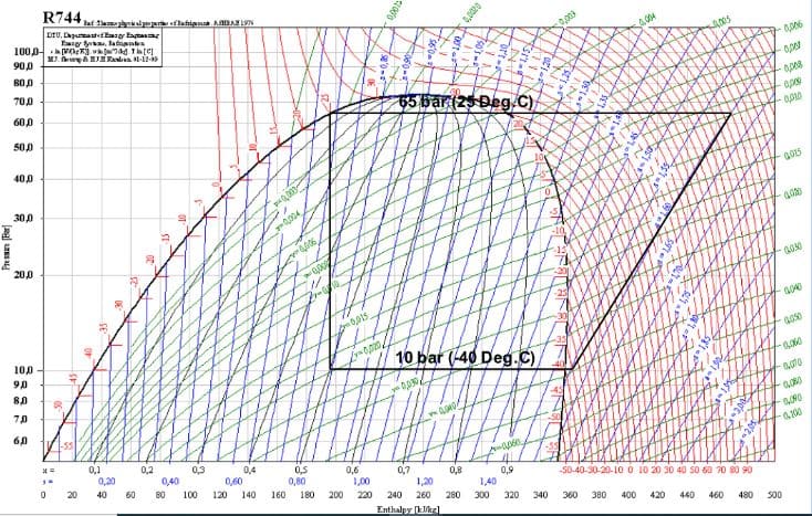
Subcritical cycles are those in which the refrigerant can be condensed, i.e. the compressor discharge pressure is lower than the critical pressure. In the Mollier diagram, the representation of a subcritical CO2 cycle is similar to that of any refrigerant, the key difference is in the pressure values and the evaporation and condensation temperatures.
As you can see in the figure below, in a cycle for low pressure, with suction at 10 bar (-40°C) and condensation at 25°C (65 bar), the discharge pressure is much higher than the one used with HFC refrigerants. In a country such as Spain, where ambient temperatures of more than 40°C are reached, it would not be feasible to use outside air to condense CO2, although condensation by water would be possible, for example. Please note that condensers and other elements must be designed to withstand such high working pressures.
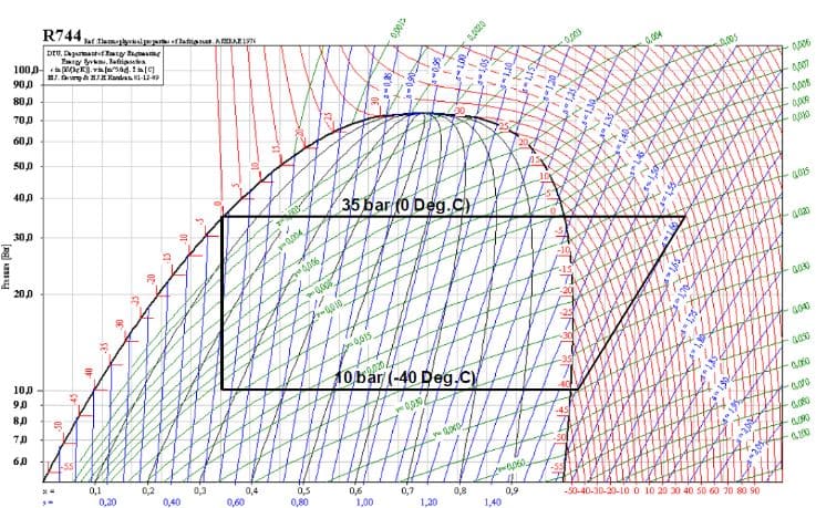
If you have a heat carrier fluid other than water, such as brine or glycol at temperatures below 0°C, or refrigerants that can evaporate at a temperature below 0°C, you could consider a lower pressure subcritical CO2 system, as shown in the following figure. The heat carrier fluid in question would exchange heat with the CO2 and condense it. As you see, the system is still valid for reaching freezing temperatures without difficulty at a reasonable pressure (10 bar). In this way, cascade systems appear with two refrigerants, where one refrigerant circuit (CO2) is condensed by the other refrigerant (R134a, R717, R290, glycol, brine, etc.).
Subcritical CO2 cycle: installation types
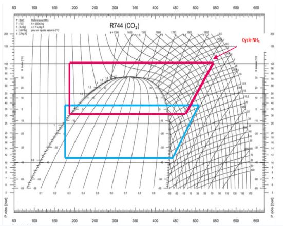
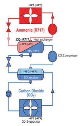
In cascade systems, the system consists of two independent refrigeration circuits. One of the circuits will contain CO2 as a refrigerant in the negative cold production areas to preserve food products where the CO2 is condensed at around -10°C with the cold produced in an evaporator from the other circuit with the other refrigerant. As an example, in the following figure, you can see the cycle of a CO2 and ammonia cascade system (R717):
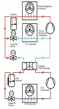
LT CO2 cascade
The “low-temperature CO2 cascade” system, such as the previous one, is characterised for being the simplest configuration that can be achieved in terms of cascade systems. In this assembly, a refrigerant (for example, HFC) is used in the high-temperature sector, which is used both to supply the medium-temperature services and to condense the CO2 of the low-temperature service circuit or freezing tunnels. All evaporators in the system work as direct expansion elements (DX).
As a variant of the above, and with the aim of minimising the HFC charge in the system, a glycol (from a chiller) can be used as a heat carrier fluid both to condense the CO2 and to supply the medium-temperature services, resulting in a “cascade system with pumped glycol for MT and LT CO2 DX”. This type of assembly is technologically simpler than the previous one. However, it is less energy efficient, as the evaporation temperature of the high temperature sector should be somewhat lower. The refrigerant charge (HFC or any other) will be lower, and you have the advantage that it will be confined within the chiller, thus minimising the risk of leaks.
Natural refrigerant cascade system with pumped CO2 for MT and LT DX.
The complete elimination of HFC from the high-temperature sector could also be considered, replacing it with a natural refrigerant, thus making a commitment to the future that respects the environment. This solution could also be combined with a pumped CO2 system to supply the medium-temperature services and a direct expansion CO2 system for the low-temperature services, thus obtaining a “natural refrigerant cascade system with pumped CO2 for MT and LT DX”:
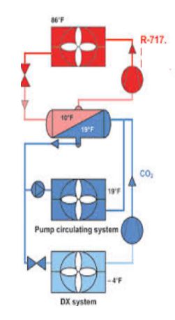
In this type of assembly, the low-temperature evaporators run as direct expansion systems, whereas the medium-temperature services run as flooded systems, with their corresponding CO2 circulation pump.
In the heat exchanger (CO2 condenser and R717 evaporator), the heat exchange needed to condense the CO2 at the cost of the evaporation of the R717 will occur.
The advantage of working with flooded evaporators is a slight improvement in the energy efficiency of the system, as in this case, it allows operation at a higher evaporation pressure in the medium-temperature services.
However, the downside is that systems that run with flooded evaporators require much more CO2 charge.
Natural refrigerant cascade system with pumped (or flooded) LT CO2.
A “natural refrigerant cascade system with pumped (or flooded) LT CO2” could also be considered, as shown in the figure below:
The difference with the previous one is that there are no medium-temperature services now, and those that run as flooded systems are now low-temperature services.
Likewise, a slight improvement in the energy efficiency of the system is obtained by increasing the evaporation temperature, but on the other hand, the CO2 charge of the installation is increased.
Subcritical cascade system with all CO2 distribution.
As a final example, a “subcritical cascade system with all CO2 distribution” could also be designed, i.e. a system where there would be a single common CO2 liquid line (it could be subcooled), both for LT and MT, and a double suction line (one for medium and the other for low temperature). The high-temperature circuit would be completely contained in the refrigeration plant, being able to use HFCs (R134a, R513A, R152a, etc.), or with natural gases, such as R290, with the major advantage that the refrigerant charge would be very low. The refrigeration diagram for the system is shown below, with this being INTARCON’s commitment in terms of medium-power subcritical plants, leading to the development of the ECO2 market product range.